4.9 KiB
Computational micromechanics of bioabsorbable magnesium stents
Journal Article: https://doi.org/10.1016/j.jmbbm.2014.01.007
Supporting Data - including original software versions: https://zenodo.org/records/11184080
If you don't have access to the paper the content is very similar to that in my thesis section 5.4, available for download at: https://researchrepository.universityofgalway.ie/entities/publication/6168a11d-5962-4e52-97d1-6f2684a97ac2
Running simulations
Abaqus User Material
The Abaqus UMAT UCrys_HCP_Only.for is used for the simulations in the paper.
In the UMAT we assume a cartesian GLOBAL axis for the overall problem and a cartesian LOCAL axis to define the orientation of the crystal. Via input properties (PROPS) 3-5 and 6-8 we specify the directions of the LOCAL x and y axes in the GLOBAL coordinate system, assuming an orthogonal LOCAL z axis given by the cross-product with 'right hand rule'.
A sample input file MATERIAL specification is shown for the UMAT:
*MATERIAL, NAME=MATERIAL-1
**
*USER MATERIAL, CONSTANTS=22, UNSYMM
45000.,0.3,1.,0.,0.,0.,0.,1.
4.,1.,0.,10.,20.,150.,7500.,40.,
260.,7500.,5.,200.,0.11,10.
*Depvar
163
*
which sets the 22 input properties. These propeties are as follows:
c     PROPS
c     1) Elastic Modulus
c     2) Poisson's ratio
c     3) x-axis orientaion in GLOBAL, x-coord
c     4) x-axis orientation in GLOBAL, y-coord
c     5) x-axis orientation in GLOBAL, z-coord
c     6) y-axis orientation in GLOBAL, x-coord
c     7) y-axis orientation in GLOBAL, y-coord
c     8) y-axis orientation in GLOBAL, z-coord
c     9) Crystal type: 1-4. FCC=1, HCP=2,3,4 (+Pyr, +Twin)
c     10) Initial slip system strength FCC or HCP Basal
c     11) FCC Hardening param
c     12) FCC/HCp Basal hardening param
c     13) Initial slip system strength HCP Prismatic
c     14) Prismatic hardening param
c     15) Prismatic hardening param
c     16) Initial slip system strength HCP Pyramidal
c     17) Pyramidal hardening param
c     18) Pyramidal hardening param
c     19) Initial slip system strength HCP Twin
c     20) Twin system hardening param
c     21) Twin system hardening param
c     22) Twin system hardening param
c
Channel Die Simulations
The channel die simulations described in the paper use CDIE_1E.inp as an input file.
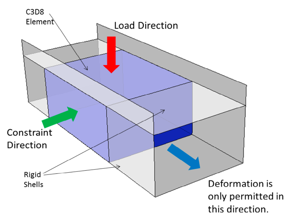
Loading and constraint directions are described via Miller-Bravais indices, which are (informally) a way to describe directions in the crystal lattice, and can be regarded as the inverted intersection coordinates of planes described in crystal-specific coordinate systems.
For the HCP material here four axes are used, three (a_1, a_2, a_3) are on one of the crystal basal planes with equal angles between them (120 degrees) and the fourth (c) is normal to the basal plane. Thus we have three coordinate systems in total:
- the HCP lattice system via MB indices
- the cartesian crystal local
LOCALsystem - the
GLOBALsystem.
In the simulated experiment the die is always closed in the GLOBAL (negative) z direction via this boundary condition in the INP file:
** Name: BC-4 Type: Displacement/Rotation
*Boundary, amplitude=Amp-1
Set-2, 1, 1, -1.
while another direction allows the the material to freely deform (GLOBAL x or y, not sure which).
To replicate the series of channel die simulations, with loading and constraint directions shown in the table below:
| Simulation | Load Direction | Constraint Direction |
|---|---|---|
| A | [0001] |
[101^0] |
| B | [0001] |
[12^10] |
| C | [101^0] |
[0001] |
| D | [12^10] |
[0001] |
| E | [101^0] |
[12^10] |
| F | [12^10] |
[101^1] |
we thus need to determine suitable crystal input orientation parameters for each test, so that the crystal is loaded and constrainted accoring to the described Miller-Bravais indices.
Determing UMAT properties for crystal orientation
Taking the first case as an example, load direction [0 0 0 1] means the loading will happen along the c axis of the crystal (or perpendicular to the basal plane). This contrains the crystal local x and y axes to be normal to the global z direction (0, 0, 1).
The constraint direction [1 0 1_bar 0] is on a plane that intercepts the hcp crystal 'a_1' axis at '1' and its 'a_3' axis at '-1'. Assuming the a_1 axis is equivalent to the crystal local x-axis, then the a_3 axis is a 240 degree rotation around the crystal local z-axis. Moving in the negative direction on the a_3 axis corresponds to a (240-180=) 60 degree rotation around the z axis, and talking the midway point (since we are moving 1 and -1 along each axis) means a 30 degree rotation about 'z'. Thus, if we want to constrain the crystal in the [1 0 1_bar 0] direction relative to a global constraint in the x direction we would need to rotate it by -30 degrees about the global z.